What Is Electrical Earthing and Why Is It Important
Electrical earthing is a protective connection between an electrical installation and the earth, made through a designed network of conductors and electrodes. It helps control dangerous voltages and gives fault current a path that allows protective devices to disconnect the supply. In a home, commercial building, factory, or utility installation, this connection is a core part of electrical safety - not a substitute for sound wiring, insulation, circuit protection, or competent maintenance.
Electrical earthing connects selected parts of an electrical system to earth through conductors and electrodes. Protective earthing keeps exposed metalwork from remaining dangerously energised if insulation fails, while system earthing establishes a reference point for the supply. When coordinated with correctly selected fuses, circuit breakers, or residual - current devices, earthing helps a fault trigger timely disconnection. Its design and testing must suit the installation, soil, fault level, and applicable standards.
What is electrical earthing?
Electrical earthing is the intentional connection of an electrical system or equipment to the mass of the earth through a conductive path. The path may include an earth electrode, an earthing conductor, bonding connections, and the installation’s protective conductors. “Electrical grounding” is commonly used for the same broad idea, especially in North American terminology; the exact terms and arrangements vary between standards and regions.
The earth is not a magic sink that makes every fault harmless. In a properly designed installation, earthing works as part of a complete protection system. If a live conductor touches an appliance’s metal casing, a sound protective path helps fault current flow so the circuit’s protective device can operate. The intended result is prompt disconnection and reduced risk of electric shock, fire, or equipment damage. Without a suitable path and correctly coordinated protection, exposed metal may remain at a dangerous voltage.
Why is earthing important?
The first reason is protection against electric shock. Many appliances and machines have conductive enclosures that are not meant to carry current in normal operation. If insulation is damaged, a loose wire or component failure can energise the enclosure. Protective earthing connects exposed conductive parts to the installation’s protective system, helping keep the fault from persisting unnoticed and supporting automatic disconnection.
Earthing also supports fire prevention. A sustained electrical fault can heat conductors, terminals, and nearby materials. A low - impedance fault path, paired with a properly rated fuse or circuit breaker, can help clear certain faults before heat builds to a dangerous level. It does not prevent every electrical fire: overloads, loose connections, arcing, unsuitable equipment, and poor maintenance require their own controls.
A grounding system can provide a stable reference for the supply and help manage transient or fault voltages. In industrial and commercial environments, bonding and earthing also help limit potential differences between interconnected metalwork. This matters around switchboards, motors, cable trays, structural steel, generators, transformers, and sensitive control equipment.
Earthing is also relevant to lightning protection and surge protection, but these functions must be designed together with the installation’s bonding and protective devices. Simply adding a rod does not guarantee protection from lightning or surges. The arrangement must be engineered for the site and comply with applicable requirements.
How does an earthing system work?
During normal operation, current flows through the intended circuit conductors. The protective earth conductor should not normally carry the load current. If a fault connects a live conductor to exposed metal, the fault current should travel through the protective path back to the source in a manner that allows the relevant protective device to detect the fault and disconnect the supply.
The complete fault loop includes more than the soil. Its route may run through protective conductors, bonding, the supply system’s earthing arrangement, and the source transformer or generator. The impedance of this loop affects the fault current and how quickly the fuse, circuit breaker, or residual - current device responds. A high - resistance electrode by itself does not necessarily mean a fault will be cleared safely, and a low earth resistance reading alone does not prove the whole installation is safe.
This is why electrical earthing must be coordinated with the supply arrangement and the protective devices. Design calculations and tests verify that conductors can withstand the expected fault conditions and that disconnection requirements are met. The appropriate method and acceptance criteria depend on system type, installation conditions, and the applicable code or standard.
Main parts of a grounding system
A practical grounding system is made up of connected components, each with a defined job:
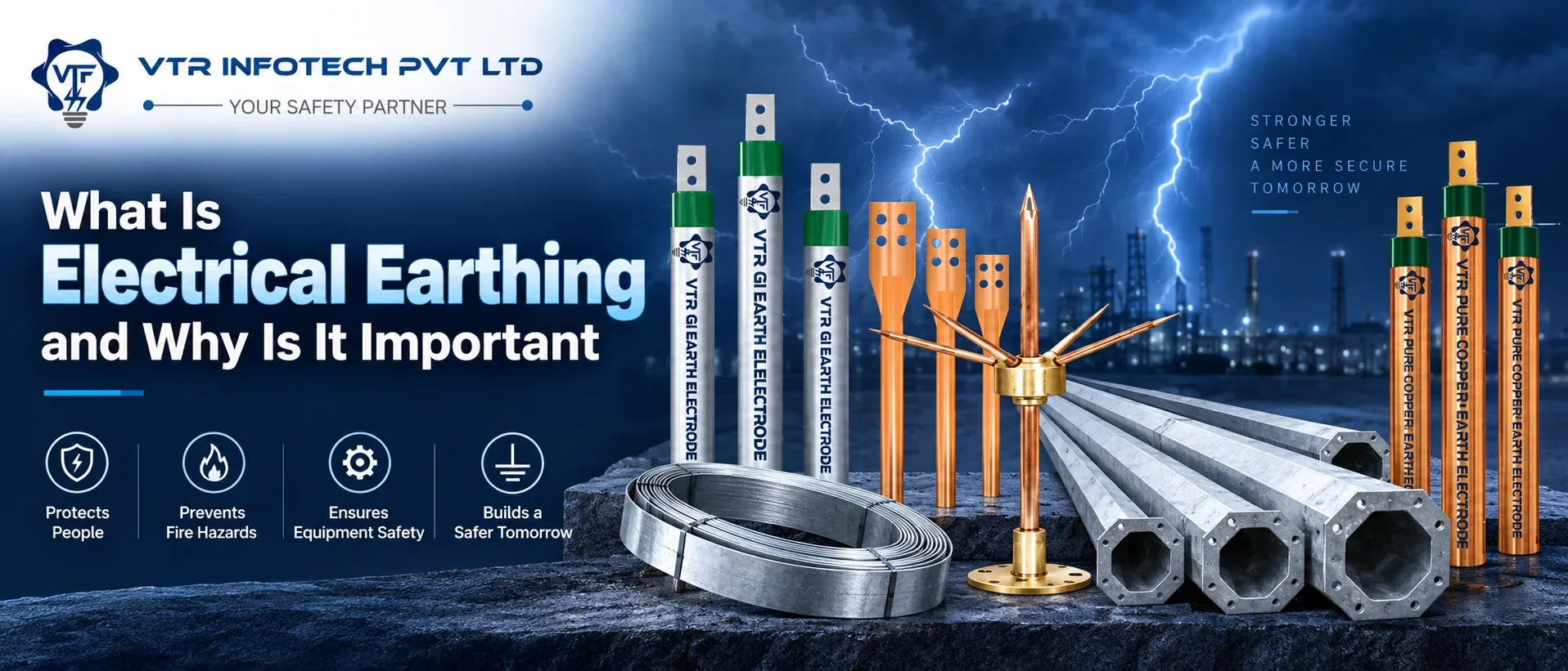
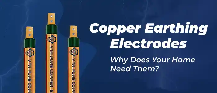
- Earth electrode: A rod, plate, strip, conductor network, foundation element, or other approved component in contact with the soil. Electrode selection depends on soil conditions, site layout, corrosion exposure, and design requirements.
- Earthing conductor: Connects an electrode or earthing terminal to the installation’s earthing network. It must be sized, routed, protected, and terminated for the expected conditions.
- Protective conductors: Connect exposed conductive parts - such as equipment enclosures - to the protective earthing system, creating a fault - current path.
- Main earthing terminal or bar: A common connection point for protective conductors and relevant bonding conductors, arranged as specified for the installation.
- Bonding conductors: Join specified conductive services or structural parts to reduce hazardous potential differences. Bonding is not a replacement for protective earthing.
- Clamps, connectors, inspection chambers, and test links: Provide mechanical and electrical continuity and allow inspection or measurement where the design calls for it.
- Every connection matters. A suitable electrode cannot compensate for a corroded clamp, an undersized conductor, a loose joint, or a missing equipment bond. Components should be compatible with each other and with the environment to limit corrosion and maintain a dependable connection over time.
Types of electrical earthing
The best - known electrode arrangements include rod, plate, strip, and foundation earthing. A driven rod can suit sites where depth is available; plates or buried strips may be used where the design, soil, or layout supports them. Foundation or structural electrodes can form part of a planned building earthing network when designed and installed appropriately.
System earthing arrangements describe how the source and exposed conductive parts relate to earth. Common international classifications include TN, TT, and IT arrangements, with subtypes. In broad terms, they differ in how the supply source is earthed and how equipment enclosures are connected to the protective system. These labels are technical, and an installer must follow the local supply configuration and applicable rules rather than choosing a type based on a generic online description.
People also use terms such as chemical earthing or maintenance - free earthing for particular electrode products or systems. Product descriptions do not replace engineering checks. Verify materials, installation method, compatibility, performance evidence, inspection needs, and compliance against the project specification. Avoid choosing an earthing method only because a supplier claims it always achieves a particular resistance value; actual performance depends on the complete installation and site conditions.
Earthing, grounding, and bonding: what is the difference?
Earthing and grounding are often used interchangeably in everyday discussion. Depending on the country or standard, “earth” may refer to the connection to the ground itself, while “ground” may also describe a reference point within an electrical system. Technical documents define their terms, so readers should follow the terminology used by their local code and project drawings.
Bonding has a related but distinct purpose. It electrically connects conductive parts that are required to be at similar potential, helping reduce the voltage difference a person could bridge during a fault. A bonding connection may link structural metalwork, services, or equipment to the main earthing terminal as required by design. Bonding does not necessarily connect every item directly to a separate earth electrode, and it does not replace protective conductors.
A safe installation relies on the combination of earthing, bonding, insulation, enclosure design, and overcurrent or residual - current protection. Treating any one of these as a complete safety solution can leave gaps.
Where is electrical earthing used?
Earthing is used in homes and residential complexes for circuits and equipment that require protective earthing under the applicable wiring rules. It is also used in offices, hospitals, data centres, retail buildings, and educational institutions, where electrical safety and continuity of essential services are important.
Factories and process plants use grounding systems for switchgear, distribution panels, motors, cable trays, machine frames, transformers, generators, and other specified equipment. Design may also address static electricity, lightning protection, instrumentation, and sensitive electronics, each with its own requirements. Commercial solar installations, telecom sites, substations, and infrastructure projects may need coordinated earthing networks that account for fault levels, equipment layout, and site conditions.
The application determines the engineering. A small residential circuit and a large industrial installation do not use one universal design formula. A qualified electrical professional should review system drawings, supply conditions, fault levels, environmental exposure, and relevant standards before specifying components or installation details.
What affects earthing performance?
Soil resistivity is one important factor. Soil composition, moisture, temperature, salts, and seasonal changes can affect how an electrode interacts with the ground. A reading taken in one season may not describe conditions throughout the year. The required measurements and interpretation depend on the design and standard being followed.
Electrode geometry and installation quality also matter. Depth, spacing, contact with the soil, joints, conductor routing, and the number of interconnected electrodes influence the overall system. Corrosion can gradually weaken a connection, especially where materials are poorly matched or the environment is aggressive. Mechanical damage from excavation or construction can interrupt an otherwise sound path.
The supply arrangement and protective - device coordination are equally important. Earthing conductor size, fault - loop impedance, device characteristics, disconnection time, and bonding all influence safety. For this reason, a single target resistance figure should not be applied blindly to every site. Design criteria must come from the applicable code, project specification, and competent engineering assessment.
Installation and testing: what should be checked?
Electrical earthing should be designed and installed by competent personnel in accordance with applicable regulations and standards. In India, IS 3043 is a key code of practice for earthing, while the Central Electricity Authority’s safety regulations and other applicable rules may also be relevant.
Inspection typically considers electrode location and accessibility, conductor size and routing, connection quality, corrosion protection, bonding continuity, identification, and coordination with protective devices. Tests may include continuity checks, earth electrode resistance measurement, earth fault loop impedance measurement, and verification of protective - device operation. Which tests are required - and how results are assessed - depends on the system and applicable standard. Testing should use suitable instruments and be documented by a qualified person.
Keep records of design drawings, test results, inspection dates, modifications, and repairs.
Common earthing mistakes to avoid
One frequent mistake is assuming that driving an electrode into the ground automatically makes an installation safe. The electrode must connect to the right earthing network, be appropriate for the site, and work with the protective devices. Another is relying on a fixed resistance number without confirming the required criterion for the specific system.
Other avoidable issues include using undersized or damaged conductors, leaving joints inaccessible, mixing incompatible metals without suitable measures, omitting required bonding, and routing protective conductors where they can be cut or corroded. Paint, rust, loose terminals, or an incorrect clamp can interrupt continuity.
Never remove an earth pin, bypass a protective conductor, or use neutral as a substitute for earth at equipment. Do not test or repair an installation while it is energised unless a competent professional is following a safe, authorised procedure. If an appliance gives a shock, a protective device trips repeatedly, or burning is noticed, stop using the affected equipment and arrange an urgent inspection by a qualified electrician.
How to choose earthing components for a project
Start with the electrical design and site conditions, not a catalogue item. Establish the supply arrangement, fault level, installation type, environmental conditions, required tests, and the applicable standards. Then confirm electrode type and material, conductor size, connection method, corrosion considerations, mechanical protection, and inspection access with the project engineer.
When comparing earthing rods, electrodes, clamps, strips, or accessories, check dimensions, material composition, coating or bonding method, compatibility between connected metals, and supporting technical documentation. Ask how the product is intended to be installed and inspected.
VTR Infotech’s product range includes earthing equipment such as rods, electrodes, earthing compounds, connectors, and related accessories. Buyers can use the project drawings and technical requirements to discuss suitable product options with the supplier. A supplier can help identify available components, while final system design, installation, testing, and statutory compliance should remain with the responsible electrical professional.
Practical maintenance checklist
A maintenance plan should match the installation’s risk, environment, and governing requirements. During planned inspections, check for visible corrosion, loose or damaged connections, disturbed earth pits, exposed conductors, missing covers, water ingress, and signs of excavation or impact. Confirm that labels and drawings still match the installed arrangement.
Record test methods, instrument details, readings, weather or soil conditions where relevant, inspection findings, and corrective work. Compare results with the original baseline and project criteria instead of interpreting one value in isolation. Review the earthing network after major equipment additions, building alterations, changes to the supply, lightning or fault events, or changes in process conditions.
Only qualified personnel should carry out electrical measurements or repairs. Isolate equipment where required and follow the site’s safe work procedure.
Frequently asked questions about electrical earthing
1. What is electrical earthing in simple words?
It is a designed conductive connection between selected parts of an electrical system and earth. It helps manage fault voltages and supports protective devices in disconnecting a faulty circuit.
2. Why is electrical earthing important?
It helps reduce electric shock and fire risks by providing a fault - current path and supporting timely disconnection. It also helps control potential differences when combined with bonding and suitable protection.
3. Is earthing the same as grounding?
In everyday use, the terms often describe the same concept. Technical definitions vary by country and standard, so use the terminology and system arrangement specified for the installation.
4. What is the difference between earthing and bonding?
Earthing connects the system or specified parts to earth. Bonding electrically connects conductive parts to reduce dangerous voltage differences between them. Both may be needed for safety.
5. Does earthing stop electric shocks completely?
No. Earthing is one part of electrical protection. Insulation, enclosures, correct wiring, circuit breakers or residual - current devices, safe work practices, and maintenance are also necessary.
6. Does an earth electrode carry current all the time?
A protective earth conductor should not normally carry load current. It may carry fault or transient current under abnormal conditions, as intended by the design.
7. What are the common types of earthing electrodes?
Common arrangements include rods, plates, buried strips or conductors, and designed foundation electrodes. The suitable option depends on soil, site layout, corrosion exposure, and project requirements.
8. What is a grounding system?
A grounding system is the connected arrangement of electrodes, earthing and protective conductors, bonding connections, terminals, and compatible accessories used to meet the installation’s design and safety needs.
9. Is a low earth resistance reading enough to prove safety?
No. The full installation must be assessed, including continuity, bonding, fault - loop conditions, protective - device coordination, and the relevant acceptance criteria.
10. How often should earthing be tested?
There is no single interval for every installation. Follow applicable regulations, the project maintenance plan, site risk, and a qualified professional’s recommendations; test after relevant changes or suspected damage.
11. Which standard applies to electrical earthing in India?
IS 3043 is a key Indian code of practice for earthing. The applicable requirements depend on the installation and may also include current CEA safety regulations and other relevant standards.
12. Can I install an earthing rod myself?
Electrical earthing design and installation should be handled by competent professionals. Incorrect placement, connection, or testing can leave the installation unsafe even if a rod is present.
13. Can neutral wire be used as an earth wire?
No. Neutral and protective earth have different functions. Do not substitute one for the other or alter the arrangement; have the system checked by a qualified electrician.
14. What should I do if an appliance gives me an electric shock?
Stop using it, avoid touching exposed metal, and have the circuit and appliance inspected promptly by a qualified electrician. Do not bypass the earth connection or protective device.
15. How do I select an earthing electrode or rod?
Use the project design and site conditions to determine type, material, dimensions, connection compatibility, and testing needs. Confirm product documentation with the supplier and final selection with the responsible electrical professional.
Conclusion
Electrical earthing is a coordinated safety measure that helps control fault conditions, reduce dangerous touch voltages, and enable protective devices to disconnect supply. Its effectiveness depends on the complete path from the equipment enclosure and protective conductor through the earthing arrangement and supply , not simply on the presence of a rod or a single test reading. For a reliable installation, follow the applicable standards, use compatible components, document inspections, and involve qualified electrical professionals in design, installation, and testing. VTR Infotech can help buyers identify earthing products for project requirements; the final system should always be validated against the project design and local compliance needs.





What Is Electrical Earthing and Why Is It Important
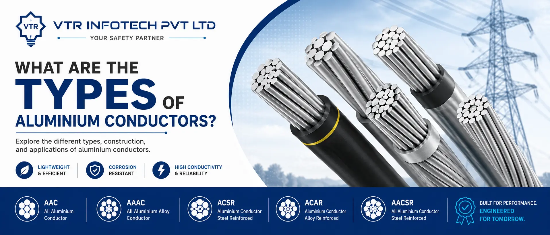
What Are the Types of Aluminium Conductors?
Efficient Air Terminal Systems
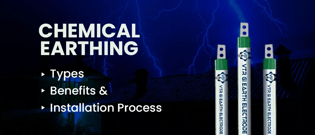
Chemical Earthing: Types, Benefits and Installation Process
Aluminum Conductors vs. Copper Conductors Pros and Cons

Copper Earthing Electrodes Why Does Your Home Need Them?